
Square and rectangular tube laser cutting can produce mounting holes, slots, end cuts and notches in hollow metal sections. These features appear in machinery frames, equipment supports, racks, furniture components and fabricated assemblies.
For a manufacturer considering a tube laser, the most useful starting point is the finished part. A mounting hole must line up with its bracket. A notch must fit the mating component. Features on opposite faces must maintain the relationship shown on the drawing.
This guide explains common applications, the details that affect processing and how to connect your part requirements to a suitable machine configuration.
Understanding Square Tube, Rectangular Tube, SHS, RHS and HSS
Square tubes have equal nominal outside width and height. Rectangular tubes have different nominal outside dimensions. Both provide several faces on which holes, slots and other features can be positioned.
You may encounter different terms in drawings and material orders:
| Term | Meaning | Where you may encounter it |
|---|---|---|
| Square tube or box section | A hollow section with a square cross-section | Fabrication drawings and general manufacturing |
| Rectangular tube or rectangular box section | A hollow section with a rectangular cross-section | Equipment frames, supports and fabricated components |
| SHS | Square Hollow Section | Structural steel drawings and specifications |
| RHS | Rectangular Hollow Section | Structural steel drawings and specifications |
| HSS | Hollow Structural Section, which can be square, rectangular or round | North American structural steel work |

For structural applications, the material specification and grade belong alongside the section dimensions. AISC’s HSS resource explains the terminology and designation of square, rectangular and round structural sections. AISC HSS resource
When reviewing a tube laser application, identify the outside width, outside height, wall thickness and stock length. Also provide the material grade and surface condition. These details help establish whether the proposed machine and cutting process are suitable for the actual stock.
Common Applications for Square and Rectangular Tube Laser Cutting
The following examples show how tube features connect to assembly requirements.
Machinery and equipment frames
A rectangular frame member may require mounting holes for guards, slots for adjustable brackets and end cuts that fit another member. The relationship between those features determines how the component locates in the assembly.
When evaluating a machine, select parts that contain the mounting and joint features your workshop produces regularly. Include a longer component if widely spaced holes are important to your work.
Racks, shelving and material handling equipment
Tubular posts, crossmembers and supports may contain repeated holes or slots. Their spacing, orientation and relationship to the tube ends can affect assembly.
For these applications, consider how part identification and sorting will work after cutting. Similar-looking components may have different hole patterns, handed features or finished lengths.
Furniture and fabricated products
Metal furniture components can include mounting openings, angled ends and notches for joining legs, rails and supports. Appearance may matter alongside dimensional fit.
Show the supplier which surfaces remain visible after assembly and which areas will receive welding, grinding or coating. A sample should be evaluated against the finished-product requirements.
Structural fabrication
Square and rectangular HSS may require connection holes, end details and openings specified by the project drawings.
For load-bearing components, hole and notch geometry should follow the approved engineering design. The cutting review should establish how the machine will produce and inspect those specified features.
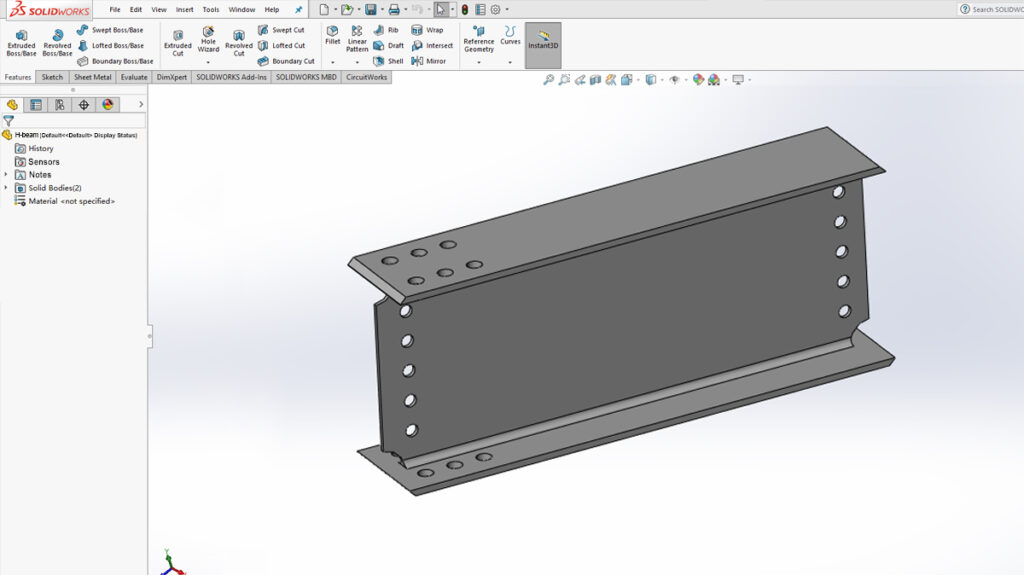
Holes, Slots and Notches Serve Different Purposes
A tube laser application can contain several types of features. Each should be assessed according to its function.
| Merkmal | Typical purpose | What to review |
|---|---|---|
| Round holes | Fasteners, pins or component mounting | Diameter, position, edge condition and alignment with mating parts |
| Elongated slots | Adjustment or locating features | Width, length, end geometry and orientation |
| Rectangular openings | Access, component clearance or specified connections | Corner geometry, dimensions and material remaining around the opening |
| End notches | Clearance or fit around another component | Mating geometry, fit-up and remaining material |
| Angled end cuts | Frame joints and connections | Finished length, angle and relationship to other features |
| Tabs and matching slots | Part location during assembly | Clearance, insertion direction and accessibility |
Round holes
A hole intended for a clearance bolt has different acceptance requirements from a hole that must locate a pin or support a threaded connection.
Identify the hole’s function on the drawing. Where threads, close fits or other specific requirements apply, discuss whether drilling, reaming or tapping will remain part of the process.
For holes on opposite tube walls, specify their alignment. If a fastener must pass through both walls, checking each hole individually may leave an important assembly requirement unverified.
There is no single minimum hole size that applies to every tube laser application. Material, wall thickness, feature geometry, machine configuration and required quality all need to be considered.
Watch the following demonstration of square tube loading and cutting on a JQ Laser 7035HTS.
Slots and rectangular openings
Slots may provide adjustment or receive a mating component. Review both the overall dimensions and the local geometry at the ends or corners.
If a slot accepts a tab, include the mating part in the review. Its thickness, coating and insertion direction affect the clearance needed for assembly.
Features close to a tube corner require particular attention because the surface transitions away from the flat face. Provide the intended position relative to the actual section geometry.
End notches
A notch can create clearance for another tube or follow the shape of a mating component. Evaluate it in the intended joint.
Check whether the parts locate as expected, whether the joint gap meets the drawing and whether the weld area remains accessible. Record any manual adjustment required before assembly.
If the design uses several interacting notches, test the complete connection. An individual cut piece provides only part of the fit-up information.
Tabs and slots for assembly
Tabs and slots can help locate parts during fabrication. Their usefulness depends on the clearance, insertion path and way the assembly is restrained.
Review the joint sequence with the people who assemble and weld the product. Confirm whether every part can be inserted, located and accessed in the required order.
Define the Relationship Between Different Tube Faces
A square or rectangular tube part is a three-dimensional component. Features may extend across adjacent faces, line up through opposite walls or have a specified orientation relative to an end cut.
A clear drawing should identify the reference face, reference end and dimensions that control those relationships.
For a rectangular section, distinguish the wide face from the narrow face. Where several similar parts are used in an assembly, show the required orientation and identify left-hand or right-hand versions.
Useful checks include:
- Hole positions measured from the specified finished end.
- Alignment between openings in opposite walls.
- Spacing between features on adjacent faces.
- Orientation of slots relative to an angled end cut.
- The relationship between a notch and the tube’s wide or narrow face.
Agree on an inspection method for the critical relationships. Measuring a hole diameter with a caliper may be straightforward, while checking a feature’s position across multiple faces may require a fixture or another suitable method.
A 3D model can help communicate the geometry. Keep the controlled drawing, revision and acceptance requirements associated with that model.
Account for Corner Radii, Weld Seams and Actual Stock
The dimensions entered into a program should represent the material you purchase closely enough for the features being produced.
Corner radii
Square and rectangular tubes commonly have rounded corners. The radius affects the transition between adjacent faces and the available flat surface near a corner.
If a hole, slot or mating detail approaches this transition, review it against the section you intend to use. The internal corner geometry also matters when another component must fit inside the tube.
Provide material information or measurements where the corner shape is important to the part.
Weld seam position
For welded tube, identify whether the seam position affects the cut features or final assembly. A drawing may require the seam to face a particular direction because of appearance, internal clearance or connection details.
The Steel Tube Institute explains that internal weld flash can interfere with close-fitting components and interior connection plates. Where your design uses an internal insert, review the seam as part of the fit check. Steel Tube Institute guidance on HSS seam welds
If seam orientation must be controlled, ask how the proposed production arrangement identifies and maintains it. Include that requirement in the application review.
Straightness, twist and surface condition
Show the supplier representative stock, including any variation you normally accept from your material supplier.
Ask how the machine holds and supports the tube, how the section is positioned for cutting and which material conditions require operator intervention. Record any stock preparation used during the trial.
For stainless steel or other appearance-sensitive work, also identify surface-finish requirements and handling marks that would affect the finished product.
Evaluate Assembly and Secondary Operations
The value of a cut feature becomes clear when the part reaches the next operation.
For a mounting component, check whether the bracket and fasteners fit. For a frame joint, check location, joint gap and access for welding. For an internal insert, verify the clearance through the required insertion length.
Document the work remaining after cutting. Depending on the part, this may include deburring, cleaning the tube interior, machining particular holes, tapping, edge preparation or surface finishing.
If bevels are specified, confirm the supported geometry for the proposed cutting head and software. Review the bevel on a representative sample against the drawing and welding requirements.
Keep as-cut samples identifiable. If a sample has been ground, cleaned or otherwise finished before inspection, record that condition so the production review includes those operations.
Choosing a Machine for Your Square and Rectangular Tube Parts
Choose the machine around a representative part list and material range. The review should cover the complete combination of cross-section, wall thickness, length, weight and required features.
Confirm square and rectangular section capacity
A round-tube diameter rating does not establish the permitted width and height of every rectangular tube.
Ask for the approved section limits for the exact configuration being quoted. Confirm the relationship between cross-section dimensions, chuck opening, rotational clearance and any nearby supports.
Also review the smallest sections in your work mix. A machine selected around the largest component still needs to grip and support the smaller tubes you intend to process.
Review i6 against your regular part mix
For manufacturers assessing square and rectangular tube components, include the i6 tube laser cutting machine in the initial model discussion.
Overview of the JQ Laser i6 tube laser cutting machine and its loading arrangement.
Provide examples of your usual mounting holes, slots and end details, together with the stock dimensions and batch quantities. Ask JQ Laser to confirm the configuration against those parts.
Include i20 when reviewing larger or heavier stock
When the application involves larger or heavier tubes, include the i20 tube laser cutting machine in the comparison.
Review the stock weight together with section dimensions and length. Confirm how the loading arrangement, supports and chucks work together through feeding, rotation and cutting. The review should also cover the receiving method for the finished parts.
Assess 12035ET for long-part handling requirements
For projects involving long tubes or finished components, review the 12035ET tube laser cutting machine alongside the required support and receiving sequence.
State the raw stock length and finished-part length separately. Include the heaviest component, the shortest cut pieces and how each will be collected. Ask which handling equipment is included in the quotation and which arrangements require further configuration.
Match power, handling and software to the job
Select laser power using the material, wall thickness, part geometry and required cut condition. Request evidence from representative parts and agreed test conditions.
Then review the surrounding workflow. Frequent section changes, long batches and mixed finished-part lengths place different demands on loading, setup and collection.
For software, ask how your drawings or models are imported and how face orientation, mirrored parts, nesting and part identification are handled. Have the supplier demonstrate the file types and functions your team expects to use.
Compare available tube laser cutting machines against your material range, part geometry and handling requirements.
Validate the Configuration with Representative Parts
Build a sample plan around the features that determine whether your parts are usable.
A mounting component might need aligned holes on opposite walls. A frame member might need an angled end and a notch whose position is controlled from that end. A longer tube might need widely spaced features that must line up in an assembly.
Agree on the drawing revision, material, sample quantity and inspection method before the test. After cutting, review both the dimensions and the fit with mating components.
| Review area | Evidence to request |
|---|---|
| Cut geometry | Identified photographs of holes, slots, corners and end details |
| Critical dimensions | Measurements associated with the drawing and individual samples |
| Assembly | Fit with mating parts or a representative fixture |
| Remaining work | A record of deburring, cleaning, machining or other finishing |
| Process time | A defined sequence showing which loading, cutting and collection stages are included |
| Configuration | The machine, cutting head, power and handling arrangement used for the test |
Where practical, review consecutive samples. Keep the original results distinguishable from any later test performed after a setting, drawing or process change.
Häufig gestellte Fragen
Can a tube laser cut holes on all four sides of a square tube?
A suitable machine and program can process features on different faces as the tube is fed and rotated. Confirm access, gripping and support for the required positions, especially near tube ends or other restricted areas.
Can laser cutting replace drilling and notching?
Laser cutting can combine several contour-cutting operations on a suitable tube part. Review each feature’s final requirements. Threads, specific fits or other characteristics may retain a separate machining operation.
How small can a hole or slot be?
The practical limit depends on the material, wall thickness, geometry, equipment and required result. Submit the feature for review and validate it with a representative sample.
Can square and rectangular tubes be bevel cut?
Bevel cutting requires a suitable cutting head, software and supported workpiece geometry. Confirm the capability for the exact machine configuration and demonstrate the specified feature.
Which matters most when choosing a tube laser?
Use the combination of section dimensions, length, weight, material and part features. Then evaluate the loading, support and receiving process against the way your workshop runs those parts.
Discuss Your Square and Rectangular Tube Application
Send JQ Laser your material grade, outside width and height, wall thickness, stock length and part drawings. Include typical batch quantities and any critical assembly, appearance or finishing requirements.
Our team will review the application and discuss a suitable machine configuration and sample-cutting scope.
