
A tube laser sample cutting test should help you answer a practical question: can the proposed machine and process produce parts that meet your production requirements?
A finished sample shows the result of one test. To judge whether that result is relevant to your workshop, you also need to understand the drawing requirements, material, machine configuration and work completed after cutting.
This guide explains how to evaluate tube laser cutting samples, check their suitability for assembly and compare test results before choosing a machine.

1. Agree on What the Test Needs to Prove
Start by identifying what would make the sample acceptable for your application. This could be the position of mounting holes, the fit of an end notch, the finished part length or the amount of edge preparation required before welding.
Confirm the material grade, tube cross-section, dimensions and wall thickness used in the test. Record any differences between the test material and your normal production stock.
Use an agreed drawing revision, with units, reference surfaces and critical dimensions clearly identified. If your drawing does not specify a tolerance or edge requirement, discuss it before cutting rather than deciding what is acceptable after seeing the sample.
For welded tube, identify whether the seam position matters to the features or assembly being tested.
Our tube laser quotation preparation guide covers the information needed for an initial equipment enquiry. For sample evaluation, the next step is to connect that information to specific checks and acceptance requirements.
2. Choose Parts That Represent Your Production
Select a regular production part and, where relevant, a part containing features that are difficult or important to your process.
Useful features to include may be:
- Mounting holes and narrow slots.
- Holes on opposite or adjacent tube faces.
- Notches and mating end profiles.
- Features close to corners or tube ends.
- Long distances between critical features.
- Bevels, if required and included in the proposed configuration.
Choose features from actual work you expect the machine to perform. A decorative demonstration sample may show a range of shapes without answering whether your production parts will fit their fixtures or assemblies.
Keep regular work and occasional demanding jobs identifiable in the test plan. A successful test on one tube size and wall thickness does not establish performance across your entire material range.
Agree on the number of samples in advance. Several consecutively cut parts can provide more useful comparison evidence than one selected piece, although a short sample run does not establish long-term production consistency.
3. Inspect Cut Edges, Holes and Critical Dimensions
Review the samples in their as-cut condition before evaluating any cleaned or finished versions. Ask whether they have been ground, polished, deburred or otherwise modified after leaving the machine.
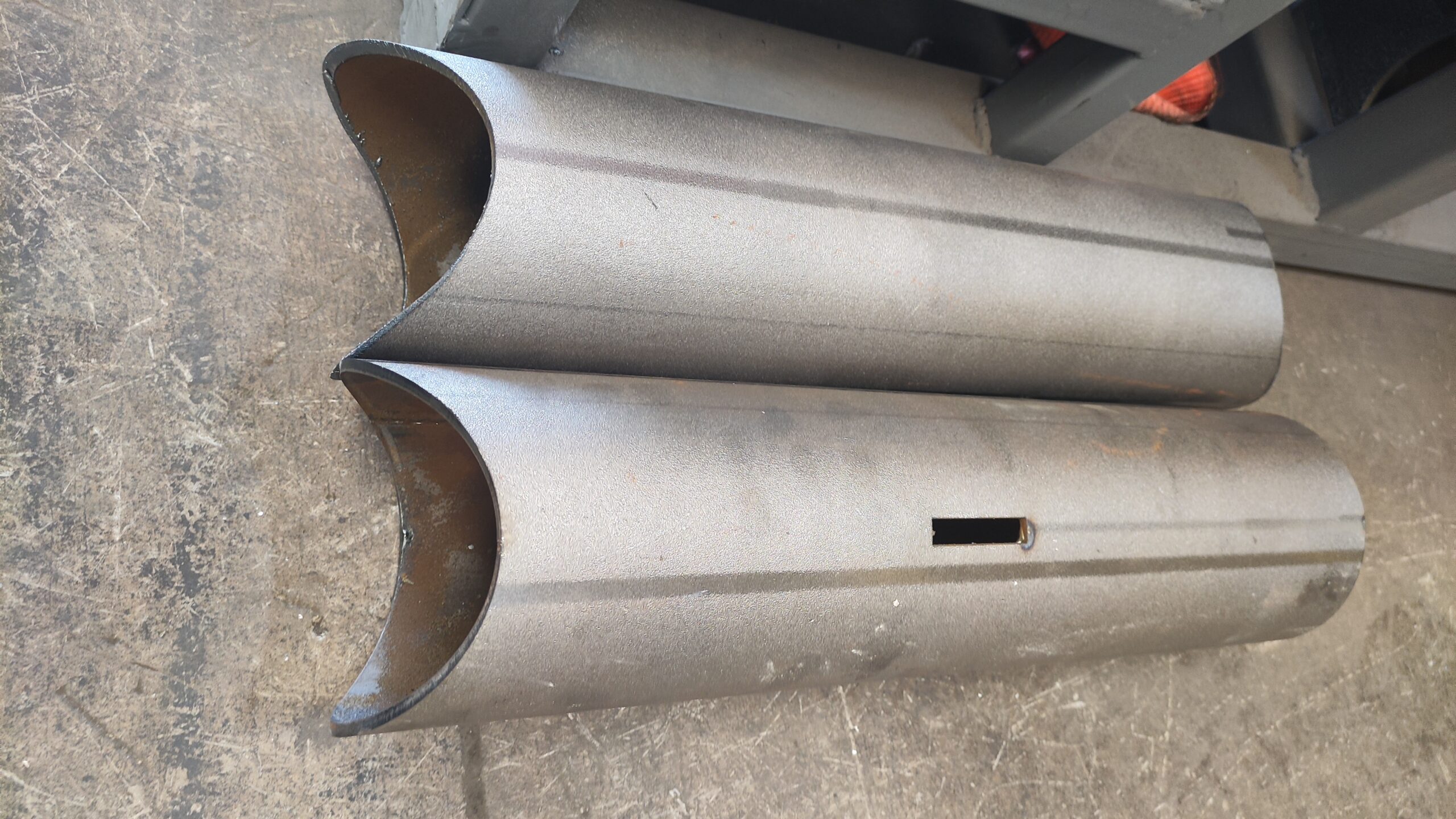
Inspect the relevant surfaces
Look at cut ends, hole edges, slots, corners and notches. Where accessible, inspect the inside of the tube and the wall opposite a cut feature.
Record attached material, burrs, visible roughness, incomplete cuts or marks that could interfere with the next operation. Judge their acceptability against your part requirements.
Photographs can document visible conditions, but they do not establish dimensional compliance. Ask for views that clearly identify the part and feature being inspected, alongside measurement records where needed.
Measure from the drawing references
Check finished part length, hole and slot dimensions, feature positions and end geometry using suitable inspection equipment.
For square and rectangular tubes, pay particular attention to the relationship between features on different faces. A hole may appear correctly positioned when viewed alone, while its alignment with another face still needs checking.
For round tubes, include the angular relationship between features when it affects assembly.
Agree on the inspection method for each critical characteristic. A caliper reading may be useful for some dimensions; positional relationships or complex end profiles may require another method.
Compare consecutive samples
Record the same critical dimensions on each agreed sample. Keep the results associated with individual part identifiers so that differences remain visible.
If a feature falls outside the agreed requirement, identify what changed before repeating the test. Keep the original and revised results distinguishable.
4. Check Assembly, Welding and Finishing Requirements
Whenever practical, evaluate the cut sample with its mating components or production fixture.
For a frame component, check whether mounting holes align and whether the part locates correctly. For a tube joint, assess the mating profile and joint fit against the drawing. Record any manual adjustment needed before assembly.
If welding is part of the process, involve the person responsible for welding requirements. Review joint geometry, fit-up and edge condition against the applicable drawing and welding procedure.
Where bevel cutting is required, inspect the specified bevel geometry on the sample and confirm which machine configuration produced it.
Also assess the work remaining after cutting:
- Is deburring required for handling or assembly?
- Does the inside of the tube need cleaning?
- Is additional edge preparation required before welding?
- What preparation is needed before painting, coating or another finishing process?
Record those operations and, if measured, their time. A sample that assembles successfully after manual correction should be documented with that correction included.
5. Understand the Test Conditions and Reported Time
Ask for a test record that identifies:
| Test detail | What to confirm |
|---|---|
| Machine configuration | Model, laser source power, cutting head and relevant options |
| Material | Grade, tube dimensions, wall thickness and surface condition |
| Assist gas | Gas type and recorded operating conditions |
| Material handling | Raw tube length, supports, loading and unloading method |
| Cutting process | Straight or bevel cutting, relevant settings and operator intervention |
| Sample condition | As-cut state and any subsequent finishing |
| Timing | Measured or estimated time, with clear start and finish points |
Check how closely the test configuration matches the machine being quoted. Record any differences that need further review.
Distinguish cutting time from production time
A video showing the laser cutting a feature may exclude loading, clamping, tube feeding, repositioning, unloading and part collection.
Ask what the reported time includes. If several operations overlap, request the elapsed time for a clearly defined sequence rather than adding individual times that occur simultaneously.
Confirm whether the figure comes from an actual run or a software estimate. For video evidence, request a continuous view of the agreed sequence where practical, with any omitted stages identified.
When comparing suppliers, use the same drawing, comparable material, agreed quality requirements and consistent timing boundaries. Record differences instead of treating unlike tests as directly equivalent.
6. Use the Results to Review the Proposed Configuration
Bring the inspection results, assembly observations and test conditions together before deciding whether the proposed setup suits your work.
The review should identify:
- Which requirements the samples met.
- Which features or processes need further testing.
- What secondary work remains.
- How the tested configuration differs from the quotation.
- Which material sizes or applications remain untested.
Keep the approved drawing revision, sample identifiers, measurements, photographs and test conditions together. These records give both parties a clearer basis for discussing the equipment.
A pre-purchase sample test supports machine selection. Final machine acceptance should follow the scope and requirements agreed for the order.
Explore JQ Laser’s tube laser cutting machines and discuss a configuration based on your parts, material handling needs and test findings.
Request a Sample Cutting Review
Send your tube dimensions, material, wall thickness and part drawings. Our team will review your application and discuss a suitable sample cutting test.
Include the features you need to verify, your assembly or welding requirements and any relevant production targets.
