
H-beam laser cutting brings several beam-processing operations into a CNC-controlled workflow. Depending on the specified machine configuration and part geometry, these operations can include cutting to length, producing holes and cutouts, preparing beveled edges, and marking parts for identification or assembly.
For steel fabricators, the purchasing decision starts with the beams and connection details they need to produce. Beam height and width matter, but so do web thickness, flange thickness, stock weight, feature location and the requirements of subsequent welding or assembly.
This guide explains how to assess those requirements and uses the JQ Laser HL-1250S to illustrate a gantry-based approach to H-beam processing.
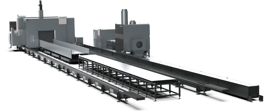
How H-Beam Laser Cutting Works
An H-beam has a web connecting two flanges. Cutting features across these surfaces requires the cutting head to reach different positions and orientations around the section.
In the HL-1250S arrangement discussed here, the beam remains stationary on its supports while the gantry travels along its length. The cutting head combines linear movement with rotary and tilting movement to approach the required cutting surfaces.
This arrangement makes workpiece positioning and support part of the cutting process. Before processing begins, the beam must be loaded, located and checked against the programmed geometry.
The equipment workflow includes material centering and contour detection before cutting. These steps help the system establish the relationship between the actual stock and the programmed part. They do not remove the need to define acceptable incoming material condition or verify the finished component.
For a shop processing both beams and hollow sections, the requirements should be reviewed separately. Our guide to square and rectangular tube laser cutting covers the hole, slot and notch considerations associated with those sections.
Common H-Beam Laser Cutting Operations
A useful machine review begins with a feature list taken from actual production drawings.
| Operation | Typical production purpose | What buyers should review |
|---|---|---|
| Straight or angled cutting to length | Produce the specified overall length and end geometry | Length, end angle, datum and inspection method |
| Hole cutting | Create connection or assembly features | Diameter, position, shape and required fit |
| Web cutouts | Produce openings or clearance features in the web | Contour, corner details and location relative to the flanges |
| End notches and coping features | Provide clearance for adjoining components | Access, internal radii and assembly fit |
| Flange bevel cutting | Prepare specified edges for a welded connection | Bevel angle, root face and subsequent preparation |
| Marking and scribing | Identify components or indicate assembly references | Mark content, position and visibility after finishing |
These operations serve different purposes. A demonstration of one feature should not be treated as evidence that every feature in a fabrication drawing is covered.
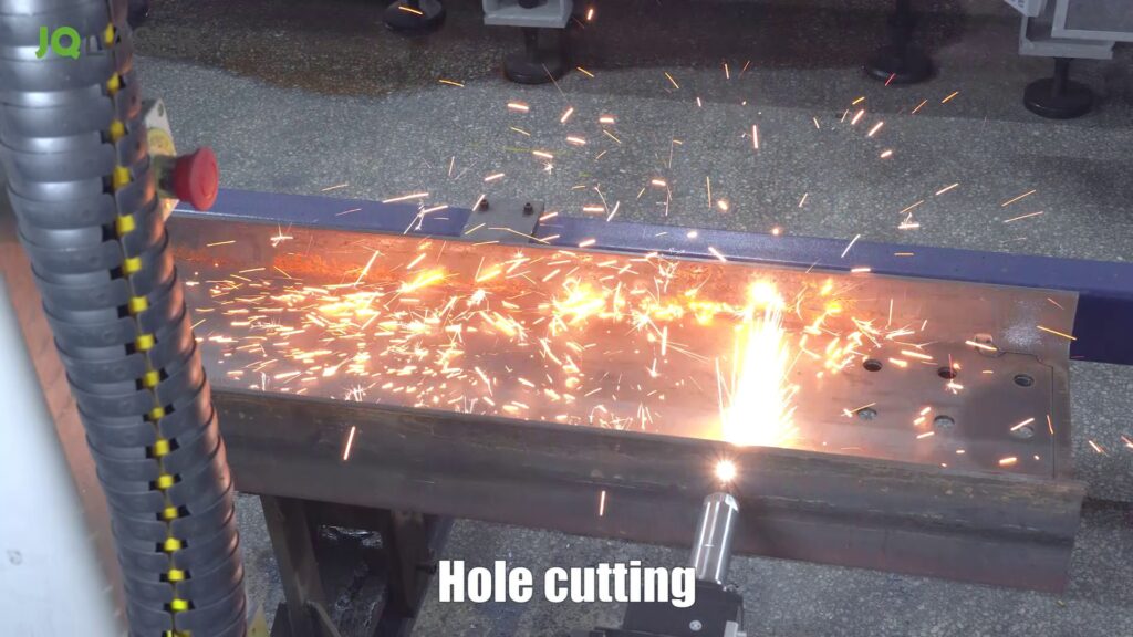
Hole Cutting
Connection holes should be assessed against the drawing and the intended fastening or assembly method.
Review the hole diameter, location from the defined datum, spacing within a pattern and relationship to other surfaces. If a component contains holes on both the web and flanges, inspect their relationship as part of the same component.
A hole that looks round in a video still needs dimensional inspection. The trial should establish whether the specified hole size, shape and position are achieved on representative material.
Where a drawing or project specification requires additional hole finishing or a particular production method, include that requirement in the application review.
Web Cutouts and End Details
Web openings, end notches and coping features can determine whether a beam fits correctly against another component.
Provide the complete contour rather than a general instruction to “cut a notch.” The review should include internal radii, nearby flange surfaces, access for the cutting head and the required clearance after cutting.
A three-dimensional model can help communicate the geometry, but it should remain associated with the controlled fabrication drawing and revision.
The HL-1250S demonstration includes web contour cutting and local opening features. For a purchasing test, select examples that represent the actual connection details your shop produces.
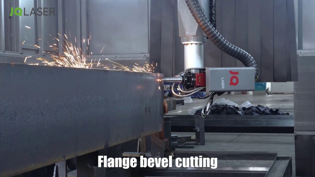
Flange Bevel Cutting
The HL-1250S video also shows flange bevel cutting.
A bevel should be evaluated as part of the specified weld preparation. Relevant details include the angle, root face, position, surface condition and relationship to the adjoining component.
The technical specification reviewed for this article lists bevel cutting up to ±45°. The usable range for an individual feature still needs to be checked against material thickness, cutting-head access, surrounding geometry and the required cut condition.
Agreement on the bevel angle alone does not establish that a part is ready for welding. Confirm whether cleaning, grinding or other preparation is required under the applicable fabrication procedure.
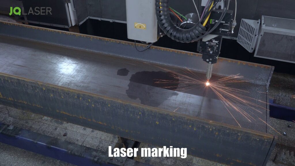
Marking and Scribing
Marking can help carry identification or reference information from the cutting stage into later production.
Before ordering, demonstrate the intended content and location. A part number, an assembly reference and a layout line may require different settings and inspection criteria.
Also consider what happens after cutting. A mark may become difficult to read after blasting, painting or other finishing. Its usefulness should be checked within the complete production route.
Define Beam Size, Thickness and Weight Separately
A beam description should include more than its nominal section designation.
The machine review should establish:
- Overall section height and flange width.
- Web thickness and flange thickness.
- Stock length and finished component length.
- Weight of the heaviest incoming beam.
- Rolled or fabricated section geometry.
- Material grade and surface condition.
Web thickness and flange thickness should be recorded separately. Features cut through these areas can present different processing conditions.
The section dimensions must also be considered together. A machine’s stated height range does not independently establish that every flange width, thickness and feature location within that height can be processed.
For long components, include the support arrangement and the planned method of lifting and removing finished parts.
Assess the HL-1250S Against Your Production Requirements
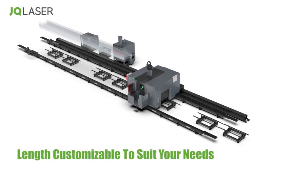
The JQ Laser HL-1250S H-beam laser cutting machine uses a gantry arrangement for processing stationary beams.
The following values describe the specific 20 kW configuration reviewed for this article. They provide a starting point for application assessment; the final quotation and technical agreement should define the machine supplied.
| Item | Reviewed configuration |
|---|---|
| Laser power | 20 kW |
| H-beam and I-beam height | 200–1200 mm |
| Section width | 100–600 mm |
| Maximum raw material weight | 5,000 kg |
| Listed bevel range | ±45°, subject to the feature and processing conditions |
| Workstation arrangement | Two workstations |
The configuration supports a discussion around cutting to length, holes, bevels, end notches, marking and scribing.
To assess its suitability, submit a representative part family. Include the largest and heaviest stock, frequently produced components, and the features that are hardest to manufacture or assemble.
This gives the application review a more useful basis than selecting a machine from one maximum dimension.
Plan Loading and Cutting as One Workflow
The documented HL-1250S workflow uses overhead-crane loading and two workstations.
While cutting takes place at one station, loading and unloading can be arranged at the other within the approved operating procedure. The gantry then moves to the next station for material location, contour detection and cutting.
The practical benefit depends on the work being processed. A short cutting program may leave limited time to remove finished parts and position the next beam. Longer programs may allow more preparation work to be completed at the other station.
Review the following conditions in the proposed layout:
- Crane access and lifting routes.
- Incoming stock and finished-part staging.
- Support positions for different section sizes.
- Access for removing offcuts.
- Operator access and the machine’s protective arrangements.
The specification includes fixed and movable support elements. Their positions should be reviewed against the sections and lengths in your production list.
A two-workstation layout should be evaluated through a complete loading, positioning, cutting and unloading sequence. It should not be assumed to eliminate all waiting time.
Check the Actual Beam Before Cutting
The geometry in a model represents the intended component. Incoming steel may differ from that geometry.
The HL-1250S specification describes contour detection using laser distance sensing. The video also introduces RTCP correction and visual calibration as part of the processing system.
For a buyer, the useful question is how the proposed configuration handles the stock the factory receives.
Use representative beams to review the locating and scanning sequence. Ask the supplier to explain which conditions can be accommodated, which require adjustment, and which fall outside the agreed incoming-material limits.
Then inspect features against the chosen datum. Confirm that the inspection method remains practical for long beams and features located on different surfaces.
Review the Software Route from Model to Cutting Program
A workable software route connects the fabrication model, cutting geometry, nesting and machine program.
The documented workflow includes conversion of Tekla model data into cutting code, nesting of individual components and a three-dimensional preview of the cutting path. The video shows NC1 file import and model display.
Tekla Structures can create part-specific .nc1 files using its NC export settings. The official Tekla documentation on creating NC files explains the export process and the settings that affect the output.
For a machine demonstration, use files from your own detailing workflow. Check whether the transferred data preserves the features that matter, including holes, end cuts, bevels and identification information.
Also review how the software handles revisions. The operator should be able to identify the current file, inspect the generated geometry and confirm that the cutting program matches the approved component.
File import alone does not establish that every feature has transferred correctly. Include program preview and a physical sample in the review.
Validate Representative Parts Before Ordering
A useful trial should test the features that determine whether your components can move into assembly.
Select a manageable group of parts covering routine work and challenging details. Depending on your production, this may include a hole pattern, a web cutout close to a flange, an angled end, a flange bevel and a marked component.
Agree on the inspection requirements before the trial.
| Review area | Evidence to request |
|---|---|
| Overall component geometry | Measurements against drawing datums |
| Holes | Size, shape, position and relevant assembly checks |
| Notches and cutouts | Contour inspection and clearance checks |
| Bevels | Angle, root face and surface-condition inspection |
| Marking | Legibility and location |
| Production sequence | Loading, locating, scanning, cutting and unloading records |
Machine positioning specifications and finished-part tolerances describe different things. Finished dimensions should be verified on the actual component under agreed test conditions.
Record the material, section dimensions, web and flange thicknesses, laser power, assist gas and relevant processing settings. If a cycle-time video is supplied, establish which activities are included in the recorded time.
Where possible, carry the sample into the next operation. Assembly and weld-preparation checks can reveal requirements that are difficult to judge from a cutting video alone.
Frequently Asked Questions
Can a laser cut holes in both the web and flanges of an H-beam?
A suitable multi-axis configuration can approach different beam surfaces. The required hole location, section geometry and cutting-head access should be checked on the proposed machine and demonstrated with representative parts.
Does a larger laser power rating guarantee that a beam is suitable?
Laser power is one part of the assessment. Section size, web and flange thicknesses, feature geometry, material condition, support and the required cut quality also affect suitability.
Does the HL-1250S rotate the beam during cutting?
In the arrangement described here, the beam remains stationary on the worktable while the gantry and cutting head move to process it.
Does bevel cutting remove all subsequent preparation?
Subsequent work depends on the drawing, cut condition and fabrication procedure. Agree on the required result and inspect a representative bevel before deciding which later operations remain necessary.
Discuss Your H-Beam Cutting Application
Start with the parts your factory needs to manufacture.
Send the beam section dimensions, web and flange thicknesses, material grade, stock lengths, component weights and representative drawings. Include the required holes, cutouts, bevels and marking details, together with your planned production quantities.
Contact JQ Laser to review your H-beam cutting application and discuss a configuration and sample test suited to those requirements.
