Equipment installation process

Host location installation
Equipment installation conditions
The distance between the side of the equipment and the wall is ≥0.5m, and the distance between the equipment exhaust fan and the wall is ≥1m.
The operating environment of the equipment is within 0~45℃
Low humidity and relatively dry (humidity within 20%~80%, no condensation)
Less dust, dust, disgust, water and other places
No flammability, corrosive gas or liquid
Will not receive too much impact or vibration
Stay away from electromagnetic fields (TIG welding equipment, etc.) Stay away from strong magnetic fields
Add water to chiller

Water quality requirements:
Circulating water allowed to be used by the chiller: purified water, distilled water, high-purity water and other softened water. It is prohibited to use oily liquids, liquids containing solid particles, corrosive liquids, etc.
Clean the filter element and replace the cooling water regularly (recommended about three months) to ensure the normal operation of the chiller.
When the ambient temperature is lower than 2℃ and the water is stored, antifreeze needs to be added to the water tank of the chiller. It is recommended to add antifreeze containing ethylene glycol and propylene glycol with a concentration of no more than 30%.
Water volume requirements:
Add water for the first time to the chiller
In the middle of the yellow line, the chiller circulates
You can then reach the green area
Shielding gas requirements
①There are two common gases: nitrogen or argon. We recommend using nitrogen for welding stainless steel. The welding effect is better. Do not use mixed/carbon dioxide gas.
②Air pressure requirements: flow meter not less than 15L/MIN, pressure meter not less than 0.3MPA, recommended gas pressure 0.15~0.2Mpa
③When welding carbon steel and galvanized sheets, it is recommended to use compressed air. It is necessary to ensure that there is no oil or water in the air.

Wire feeder power supply installation
The four-core aviation plug provides 24V power supply; it is connected to the wire feed port of the control system to provide wire feed signals.
Wire feeder wire installation

Wire feeder device installation
①Use M412 internal angle screws to tighten the wire feed adapter block, and control the wire feed angle by adjusting the angle of the adapter block; ②The distance of the straight wire feeding tube can be adjusted by telescopic wire feeding tube and fixed by nut; ③Use M54 jackscrew to lock the wire feed hose

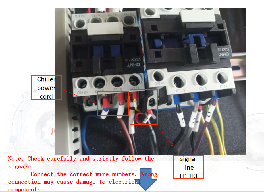
Power cord connection
1000W 1500W 2000W The input voltage of the equipment is single-phase 220V 50HZ. The wire number corresponds to L live wire N neutral wire PE ground wire
The input voltage of the 3000W equipment is three-phase 380v 50HZ. The wire number corresponds to U V W live wire N neutral wire PE ground wire.

Device boot sequence

System installation
Laser installation


Laser head installation
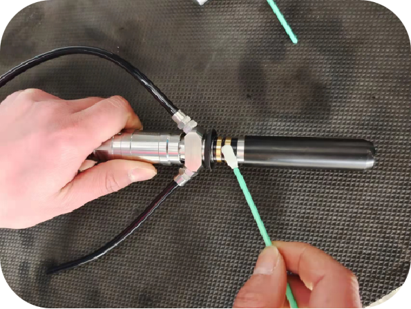
1.Fiber optic and gun tip assembly
(1) The fiber head needs to be laid flat during the entire process to prevent dust from falling on the crystal surface;
(2) Gently pull out the protective cap of the fiber head, and wipe the outside of the mechanical structure of the fiber head with a cotton swab or lens paper dipped in absolute alcohol (absolute ethanol);
(3) In a relatively clean environment, remove the protective cap of the optical fiber head crystal and illuminate the crystal with a strong flashlight to check whether there is any dirt. If there is dust, wipe it clean with a dust-free cotton swab dipped in absolute alcohol; if there are burning spots, contact us immediately
(4) Remove the QBH protective cap and nozzle of the laser head, point the laser head at the sun or a strong light flashlight, and observe with your eyes on the other side to see if the inside of the laser head is clean.
Warning: The removal of the fiber head protective cap and the installation of the cutting head must be performed in a dust-free and windless environment to avoid dust falling into the fiber head crystal.
Necessary list: absolute alcohol, dust-free cotton swabs, bright flashlight, dust-free cloth, rubber finger cots
Prohibited: Blowing with your mouth is prohibited! Do not touch the crystal with your hands! It is prohibited to wipe the optical fiber head with water!
①Take out the laser head and place the laser head and optical fiber horizontally on the table

Take out half of the optical fiber dust cap to see if there is any dust. If there is any dust, clean it with a cotton swab.
Completely take out the optical fiber and check whether there is any dust on the window lens. Do not blow air.

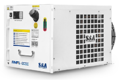
Chiller installation
Unpack the package and find the water pipes that come with it, and connect the power lines to the corresponding locations;
Add an appropriate amount of water according to the marked volume of the chiller, and add it to the standard position of the water column display.
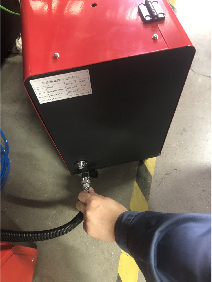
Connect the normal temperature outlet water and normal temperature return water of the chiller to the water inlet and outlet as shown below respectively, and then connect them to the laser head
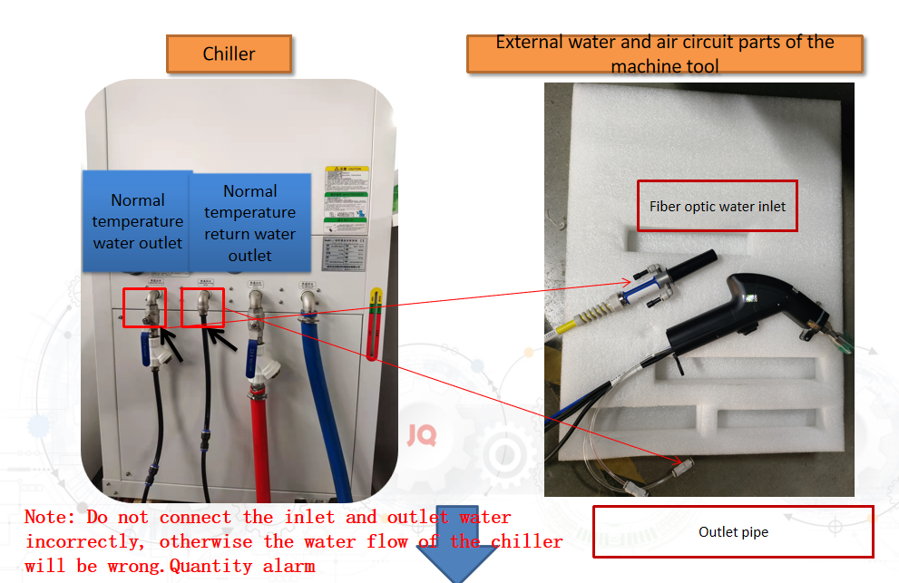
Connect the power cord of the chiller to the electrical control cabinet as shown below